---
Motorized projection screen control should be planned with the screen, projector, room controller and service route. A screen may support more than one control method, but the correct interface depends on the exact model, motor, controller and project wiring standard.
This guide helps AV integrators, electrical contractors and project buyers prepare a control specification without assuming that RF, IR, trigger, dry contact or RS-485 are interchangeable.
This guide is for AV integrators, distributors, contractors and project buyers who need a documented selection and project-planning path for this topic before requesting a quotation.
Describe what the room should do:
This sequence shows whether the project needs a local switch, remote control, projector trigger, dry contact, serial control or a combination. It also identifies what should happen if the controller, network or remote is unavailable.
| Method | Typical project role | Confirm before approval |
|---|---|---|
| RF remote | Local wireless operation | Frequency, receiver and range conditions |
| IR control | Local or equipment-rack control | IR receiver position and command compatibility |
| Projector trigger | Screen follows projector state | Trigger voltage and exact model compatibility |
| Dry contact | Relay or room-control command | Contact logic, relay rating and wiring |
| RS-485 / serial | Integrated control and status workflow | Protocol, addressing and command list |
| Building-control interface | Centralized room or facility control | Gateway, commissioning and fallback operation |
The table is a planning framework, not a product promise. Confirm the exact supported method in the current model documentation.
Control cannot correct a poor product selection. First decide whether the room needs a standard electric screen, a tab-tensioned screen, an in-ceiling screen or a fixed frame.
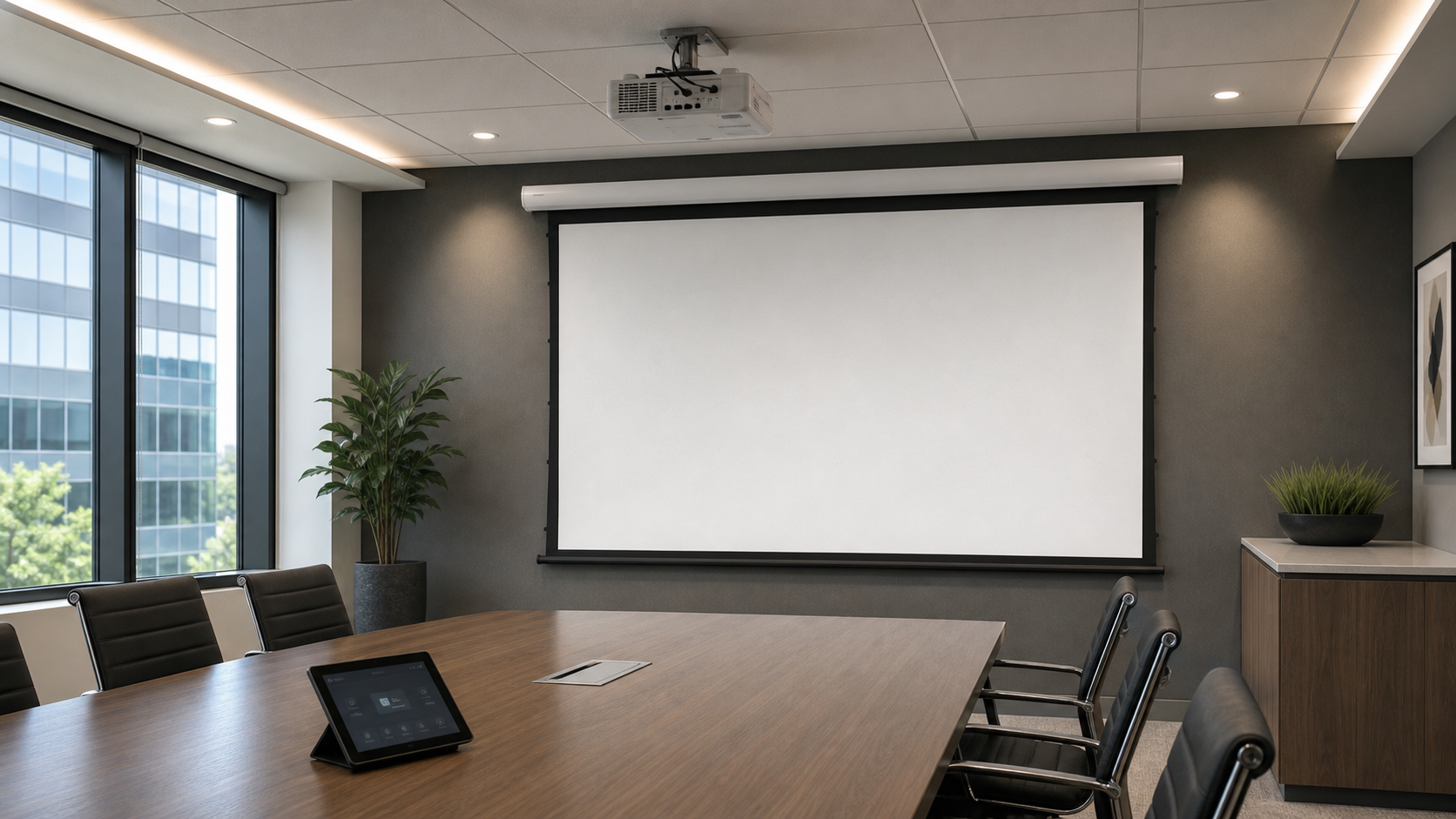
For a general presentation room, compare the standard electric projection screen. If the ceiling must remain clean, review the in-ceiling electric screen and its rough-in requirements. If flatness is a key project concern, compare the tab-tension electric screen.
Use the conference room application page to align screen operation with the room workflow.
Before walls or ceilings close, document:
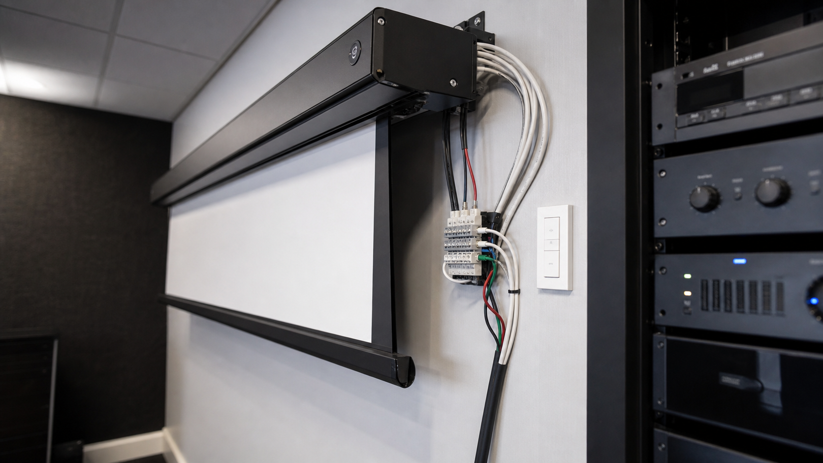
Never infer terminal definitions from another model. Ask for the current wiring diagram, installation manual and commissioning sequence for the selected screen.
The commissioning process should verify the up and down limits, bottom-bar position, fabric path, housing level, control commands and emergency stop or isolation procedure. The installer should also confirm that furniture, lights, HVAC airflow and architectural elements do not interfere with deployment.
Use a staged test instead of connecting the room controller on the first power-up. First verify the screen locally with the manufacturer’s instructions. Then test the controller or relay with the screen isolated from the final room sequence. Next test the projector trigger or serial command, followed by the complete room workflow. Record the expected state after a power interruption and define how an installer can operate the screen locally during service.
Keep the screen model, wiring revision, controller model and command list together. If the project uses several rooms, label each endpoint and keep an as-built record. A control fault is easier to diagnose when the installer can distinguish a power problem, a signal problem, a limit problem and a mechanical obstruction.
The most common risks are mismatched terminals, undocumented polarity, a controller that does not support the screen’s command logic, a concealed receiver, an inaccessible isolation point and a room sequence that starts the projector before the screen is ready. These risks are reduced by using the current wiring diagram, testing the exact model and keeping service access visible on the drawing.
For concealed installations, coordinate the access panel and test the screen before finishing. The motorized screen installation and troubleshooting hub provides supporting content for rough-in and fault checks.
Provide the project team with:
For OEM or repeated projects, keep the model name, drawing revision and control document version aligned. Factory and project context can be supported by Factory & Production, and a technical request can be sent through Contact.
| Symptom | First checks |
|---|---|
| Screen does not move | Power, isolation, controller output and local switch |
| Screen moves in one direction only | Command logic, limit state and wiring |
| Remote works intermittently | Receiver position, battery, interference and range |
| Screen stops early | Limit setting, obstruction and mechanical resistance |
| Controller reports no response | Address, protocol, cable continuity and gateway |
Do not repeatedly operate a screen that stops against an obstruction. Isolate the power and follow the model-specific service procedure.
MGF can compare suitable product directions once the project brief confirms visible image size, aspect ratio, projector geometry, material direction, mounting condition, control requirements, quantity and destination market. The final quotation should identify the exact model, compatible material, drawing and approval information rather than treating a generic guide as a product specification.
No. RS-485 requires the exact supported protocol, terminals, addressing and command documentation.
Not necessarily. Confirm the signal type, voltage, polarity and relay requirements for both devices.
The route can be planned early, but final termination should follow the approved model diagram and installation manual.
Test local control, integrated control, up/down limits, safe stop, power isolation, service access and the final operating sequence.
Send the screen model or target product family, room-control platform, wiring standard, projector model and installation drawing to MGF Screens. Compatibility should be confirmed before procurement and before the ceiling is closed.
