In-Ceiling Motorized Projection Screen Installation Checklist
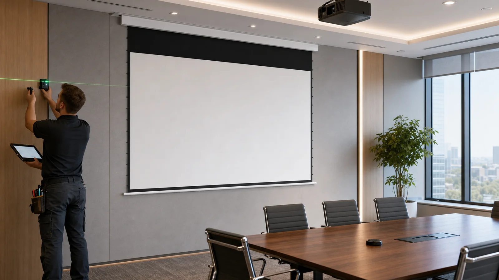
An in-ceiling motorized screen should be coordinated before the ceiling is closed. The installer needs the approved model drawing, structural support, opening and clearance dimensions, finished image position, electrical supply, control route and future service access. A ceiling grid or decorative panel is not automatically a structural mounting point.
Do not cut the ceiling from a nominal screen diagonal. The visible image, black borders, drop, bottom bar, housing and mounting points are different dimensions. Use the technical drawing for the exact ordered model and size.
In This Guide
Who This Checklist Is For
This guide is for:
- AV integrators and system designers;
- architects and interior designers;
- ceiling, electrical and general contractors;
- distributors preparing project submittals;
- facilities teams reviewing service access;
- project buyers approving an installation package.
For overall product selection, review MGF’s electric projection screen range and conference room projection solutions.
Installation Phases at a Glance
Installation Sign-Off Checklist
Use this table as a site record. Mark one result, write the evidence or deviation in Notes, assign the responsible party and obtain a dated sign-off. The downloadable CSV and PDF versions provide space for a fuller site record.
| Check item | Result | Notes / evidence | Responsible party | Date / sign-off |
|---|---|---|---|---|
| Exact model, size and approved drawing match the packing list | ☐ Pass ☐ Fail ☐ N/A | ________________ | AV contractor | ________________ |
| Independent structural support and load path are complete | ☐ Pass ☐ Fail ☐ N/A | ________________ | General contractor | ________________ |
| Ceiling opening, trim, level and access dimensions match the drawing | ☐ Pass ☐ Fail ☐ N/A | ________________ | Ceiling contractor | ________________ |
| Power, grounding, isolation and circuit protection are complete | ☐ Pass ☐ Fail ☐ N/A | ________________ | Electrician | ________________ |
| Control wiring, receiver location and fallback control are tested | ☐ Pass ☐ Fail ☐ N/A | ________________ | AV integrator | ________________ |
| Sprinklers, lights, HVAC, speakers, cameras and access panels are clear | ☐ Pass ☐ Fail ☐ N/A | ________________ | General contractor | ________________ |
| Lift plan, temporary support, trained personnel and PPE are in place | ☐ Pass ☐ Fail ☐ N/A | ________________ | Installer | ________________ |
| Housing is level, secure and not twisted; moving parts are clear | ☐ Pass ☐ Fail ☐ N/A | ________________ | Installer | ________________ |
| Upper and lower limits, bottom-bar position and full cycles pass | ☐ Pass ☐ Fail ☐ N/A | ________________ | Installer | ________________ |
| Projected grid and real content are centered and aligned | ☐ Pass ☐ Fail ☐ N/A | ________________ | AV integrator | ________________ |
| Final photos, as-built drawing, serial record and owner handover are complete | ☐ Pass ☐ Fail ☐ N/A | ________________ | Project manager / owner representative | ________________ |
| Phase | Required output | Do not proceed until |
|---|---|---|
| Design | Screen type, image size and centerline | Projector, seating and architecture agree |
| Submittal | Approved model drawing and control schedule | Dimensions and interfaces are confirmed |
| Rough-in | Structure, power, control and access | Screen load and service route are coordinated |
| Ceiling closure | Opening, trim and obstructions checked | Housing is level and deployment path is clear |
| Commissioning | Limits, controls and image alignment tested | Full operating cycle passes safely |
| Handover | Drawings, instructions and product records | Owner understands operation and access |
Before You Select the Screen
1. Confirm the Image Size and Aspect Ratio
Start with the visible image width and height. Check the farthest viewer, content detail, projector throw and ceiling height. Then choose the aspect ratio—commonly 16:9 or 16:10 for modern presentation systems, with 4:3 retained where a project requires it.
MGF’s current product matrix lists 4:3, 16:9 and 16:10 directions for its concealed in-ceiling electric screen, with 100-inch and 120-inch sizes shown in the supplied catalog range. Treat these as reference configurations; confirm the current model and all dimensions during quotation.
2. Decide Between Standard and Tab-Tensioned
A standard recessed electric screen provides concealed storage and straightforward deployment. A recessed tab-tensioned screen adds side tension where a flatter retractable surface is a higher priority.
MGF’s in-ceiling tab-tension electric screen is a reference direction for premium residential, meeting and integrated AV projects. The selected material, projector geometry and screen size still need project-specific confirmation.
3. Freeze the Projector and Image Centerline
Coordinate the lens position, throw distance, image width and vertical lens shift. Confirm that the screen deploys on the intended image plane without interfering with:
- displays or artwork behind the screen;
- tables, millwork or lecterns;
- speakers and cameras;
- ceiling lights and sprinkler heads;
- HVAC diffusers;
- doors and movable partitions.
Avoid relying on digital keystone correction to solve a mechanical alignment problem.
Model Data Package to Request
Do not treat a generic product page as the installation authority. For the exact model, size, material, voltage and control package, request and archive these documents:
| Document | Minimum content to verify | Source / approval action |
|---|---|---|
| Datasheet | Model code, visible image area, housing dimensions, size range, material, voltage, power and weight. | Request the current file with the quotation; compare it with the purchase order. |
| Technical Drawing | Housing, ceiling opening, trim, mounting points, anchors, black drop, bottom-bar position, clearances and load path. | Request the revision for the exact size; architect and contractors sign the submittal. |
| Wiring Diagram | Supply voltage, grounding, isolation, circuit protection, control terminals, receiver and low-voltage routing. | Electrician and AV integrator approve against local code and the control schedule. |
| Installation Manual | Support method, lift sequence, fasteners, adjustment limits, safety warnings, service access and commissioning steps. | Installer uses the model manual at the workface; do not substitute a similar model. |
| Warranty and Service Terms | Coverage, exclusions, motor/control parts, response route, spare parts and access requirements. | Attach the current order warranty and service contact to the handover package. |
| As-Built and Commissioning Record | Measured opening, support, wiring, limits, cycle results, image alignment, photos and sign-offs. | Owner or facilities team receives the final record before project closeout. |
MGF’s in-ceiling tab-tension electric screen is a reference product direction; confirm whether the selected project uses that or another exact series before requesting documents.
Pre-Installation Submittal Checklist
Obtain and approve:
- exact product code and screen size;
- visible image dimensions;
- overall housing dimensions;
- ceiling opening and trim dimensions;
- mounting-point locations;
- product weight and structural load path;
- required clearances above and beside the housing;
- black drop and finished bottom-bar position;
- surface type and orientation;
- supply voltage and electrical diagram;
- control interfaces and accessory list;
- motor and control service location;
- packaging dimensions and site delivery route.
Record the drawing revision. If the model, size, material or control package changes, review the ceiling opening and rough-in again.
Structural and Ceiling Coordination

4. Provide Independent Structural Support
Attach the screen to a suitable structural system designed for the product load and local requirements. Do not assume acoustic tile, gypsum board or a suspended ceiling grid can support the screen.
The contractor should confirm:
- fixing method and anchor type;
- load distribution;
- seismic or safety requirements where applicable;
- vibration isolation if nearby equipment creates movement;
- access for tightening and inspection;
- a safe installation method for the product’s length and weight.
5. Verify the Recess and Opening
Build the recess from the current approved drawing, not from a website image. Measure the real opening after framing and before finish work.
Check:
- length, width and depth;
- squareness and level;
- trim position relative to finished ceiling;
- removable panels or access hatches;
- space for cable bends and connectors;
- clearance for the roller, motor and end brackets;
- the full path of the screen and bottom bar.
Where possible, dry-fit or mark the housing outline before final ceiling closure.
6. Protect Future Service Access
A concealed product still needs inspection and service. Do not permanently close the motor, control receiver, wiring connections or mounting fasteners behind decorative finishes.
Agree who can remove the trim or access panel and what nearby components must remain movable. Include this information in the as-built drawing.
Site Readiness, Tools and Safety
Complete these controls before lifting or energizing the screen:
- assign the installer, electrician, AV integrator, general contractor and owner representative;
- prepare a suitable lift, temporary support, level, tape, approved anchors, torque tools and manufacturer-specified fasteners;
- wear required PPE for lifting, electrical work, overhead work and dust-producing construction;
- complete Lockout/tagout and verify the circuit is de-energized before wiring or service;
- coordinate ceiling fire rating, fire stopping, access panels and inspection openings;
- check sprinkler heads, lighting, HVAC, speakers, cameras, ducts and access routes before closure;
- finish dust-producing work and clean the recess before final commissioning;
- photograph support, wiring, product label and access before the ceiling is closed.
Electrical and Control Coordination
7. Confirm Power Requirements
Electrical work must follow the supplied diagram and local code. Verify voltage, circuit protection, isolation method, grounding, cable type and connection location for the selected model.
Keep mains and low-voltage control wiring separated as required. Do not energize the product while installation wiring is incomplete or while the deployment path is obstructed.
8. Define the Daily Control Workflow
Decide how the user will operate the screen:
- wireless remote;
- wall control;
- app or voice integration where configured;
- USB trigger or AV control integration where configured;
- a local service control or fallback method.
MGF’s supplied product information lists wireless remote and model-dependent voice, app and USB-trigger directions for selected concealed electric products. Confirm the exact included and optional components on the quotation and wiring schedule.
Avoid placing receivers inside metalwork or inaccessible voids without testing signal performance.
Physical Installation
9. Inspect the Product Before Lifting
Before installation:
- Confirm the product code and size against the packing list.
- Inspect the housing, trim, bottom bar and surface for transport damage.
- Verify accessories and control components.
- Keep the surface protected and rolled until the product is secure.
- Plan the lift with enough trained people and suitable equipment.
Never lift the screen by the fabric or bottom bar.
10. Level and Secure the Housing
Install the housing to the approved mounting points. Check level along the full product length and verify that the housing is not twisted. Uneven mounting can affect deployment, bottom-bar alignment and surface tracking.
Tighten fasteners to the specified method, maintain trim alignment and confirm the opening does not press against moving parts.
11. Complete Wiring and Initial Test
With the area clear, connect power and controls according to the product documentation. Perform a controlled short movement first. Listen for abnormal noise and verify that the bottom bar travels freely.
Do not repeatedly change motor limits without authorization. Incorrect adjustment can pull the surface too far into the housing or allow excessive deployment.
Quantified Commissioning and Acceptance
Use this project baseline unless the exact model manual, approved submittal or local code requires a stricter condition. Record the measured result rather than writing only “works.”
| Test | Test condition | Pass / Fail standard | Evidence and final approver |
|---|---|---|---|
| Run count | Perform 3 complete down-and-up cycles with the deployment path clear. | No binding, contact, unexpected stopping or change in tracking across all cycles. | Record cycle count; Installer and AV lead |
| Abnormal noise and contact | Listen during start, travel and stop with the room quiet. | No scraping, rubbing, rattling, repeated clicking, impact or abnormal vibration; compare with the approved sample or manual. | Record location and audio/photo evidence; Installer |
| Bottom-bar level | Measure left-to-right difference when fully deployed and record the value in mm. | Within the exact drawing/manual tolerance; if no numeric tolerance is supplied, obtain written project acceptance before handover. | Record measured mm; Installer and owner representative |
| Upper and lower limits | Run to both programmed stops with trim, housing and furniture clear. | No overtravel, housing impact, incomplete drop or unsafe bottom-bar position; record stop positions. | Record limit settings; Installer |
| Control response | Test the primary control three times, then test the fallback method. | Movement begins within 2 seconds as a project baseline, or within the agreed control specification, with no missed or contradictory commands. | Record measured response and control type; AV integrator |
| Image alignment | Project a grid and real content after the screen is fully settled. | Image centerline and visible area match the approved drawing; record any offset in mm and do not solve structural misalignment with excessive keystone. | Photo of grid and sign-off; AV lead and owner |
| Final acceptance | Review the checklist, documents, photos, as-built drawing and owner instructions. | All open deviations have an owner and due date; final acceptance is dated and signed. | AV lead, installer and owner/facilities representative |
Commissioning Checklist
Run at least one complete down-and-up cycle while checking:
- smooth and consistent movement;
- upper and lower stop positions;
- bottom-bar level;
- surface tracking and visible wrinkles;
- clearance from ceiling trim and furniture;
- remote, wall and integration controls;
- fallback operation;
- projector image alignment and overscan;
- screen orientation where the material is directional;
- abnormal noise, vibration or contact.
Project a grid and real content. Confirm the image fits the visible area without using excessive keystone correction.
Handover Package
Give the owner or facilities team:
- approved product drawing;
- electrical and control diagram;
- product code and serial record where available;
- operating instructions;
- limit-adjustment restriction;
- cleaning and care guidance;
- access-panel location;
- installer and supplier contact details;
- current warranty and service terms from the order documents.
Take photographs of the concealed structure, wiring route and product label before the ceiling is fully closed.
Common Installation Mistakes
- Cutting the ceiling from the diagonal size;
- supporting the housing from the ceiling grid;
- closing the ceiling before model approval;
- leaving no motor or control access;
- confusing visible image width with housing width;
- mounting the housing out of level;
- routing power through the moving screen path;
- assuming every control option is included;
- setting the image too low behind furniture;
- commissioning before dust-producing work is finished.
FAQ
Can an in-ceiling screen be installed after the ceiling is finished?
It may be possible if suitable structure, power, opening dimensions and access can be created, but recessed products are much easier and safer to coordinate before ceiling closure.
How large should the ceiling opening be?
Use the approved technical drawing for the exact ordered model. The opening cannot be calculated reliably from the screen diagonal alone.
Does the screen need a dedicated power circuit?
Follow the product electrical documentation and local code. Circuit and isolation requirements vary by project and destination market.
Should the motor be accessible after installation?
Yes. The motor, controls, wiring connections and mounting points should remain serviceable without destructive ceiling work.
When should I choose a recessed tab-tensioned screen?
Consider it when the screen must disappear into the ceiling and flatter retractable surface performance is important. Confirm projector, material, size and service requirements together.
Request an Installation Review
Send MGF the room drawing, ceiling section, projector model, visible image size, aspect ratio, screen type, power and control requirements, quantity and destination market. Request the current model drawing before framing or cutting the ceiling.
Contact MGF Screens for an in-ceiling projection screen configuration.