Motorized Projection Screen Wiring and Pre-Wire Guide
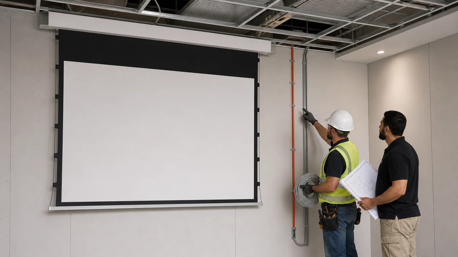
The best time to solve motorized projection screen wiring is before the ceiling closes. At that stage, power, control and service access are inexpensive to coordinate. After finishes are complete, a missing cable route can turn a simple screen into a retrofit problem.
This guide covers planning and coordination, not live electrical connections. Wiring methods, conductor sizes, overcurrent protection, separation and termination must follow the exact screen wiring diagram, local electrical code and qualified installers for the destination market.
In This Guide
Information Required Before First Fix
Do not wire from a generic product photo. Obtain or confirm:
- exact screen model and size;
- motor/control configuration;
- rated voltage and frequency for the order;
- power-entry location and whether the product is corded or hardwired;
- control interfaces included or optional;
- housing, brackets and access-panel arrangement;
- screen travel direction and finished-ceiling position;
- model-specific wiring and installation documents.
If the model has not been selected, route accessible pathways and agree a temporary basis of design. Record assumptions so the final product is checked before connection.
Power and Control Are Separate Design Decisions
| Circuit or pathway | Purpose | What must be confirmed |
|---|---|---|
| Mains power | Supplies motor and controller | Voltage, entry point, disconnect/access and local code |
| Wall-switch path | Local up/stop/down operation | Switch type and whether circuit is mains or low voltage |
| Trigger cable | Projector-driven automation | Compatible output, input and any interface module |
| Dry-contact cable | Relay/control-processor operation | Interface availability and contact behavior |
| Serial/control bus | Addressed or programmed integration | Protocol, topology, cable and termination requirements |
| Spare conduit/pathway | Future control option or replacement | Route, capacity, pull access and fire stopping |
The interface set varies by motor and controller. MGF product information lists wireless control and selected smart-control options on certain models; dry contact, trigger and serial control must be confirmed for the quoted configuration.
Coordinate the Screen Location
Mark the visible image centerline, housing position, power-entry end and service side on the coordinated reflected ceiling plan. Check structure, sprinklers, lights, ducts, projector sightline and ceiling access.
For recessed screens, use the full process in our in-ceiling installation checklist. The trim opening must not become the only access to components that require removal or adjustment.
Plan the Power Route
The electrician should confirm the correct supply, protective device, isolation method, cable type and termination enclosure from the model documentation and local code. Keep the connection accessible as required; do not bury plugs, junctions or controllers behind inaccessible finishes.
Avoid these planning assumptions:
- every screen uses the same voltage or wiring method;
- a remote-control model needs no serviceable power connection;
- the power entry can be swapped to either end on site;
- a ceiling outlet can sit anywhere above the housing;
- screen and projector should automatically share a circuit.
Plan the Control Route
Decide how the room will be operated. A remote may suit a standalone room; a shared classroom or boardroom may need a wall control; an integrated room may use trigger, dry contact or serial control where the ordered interface supports it.
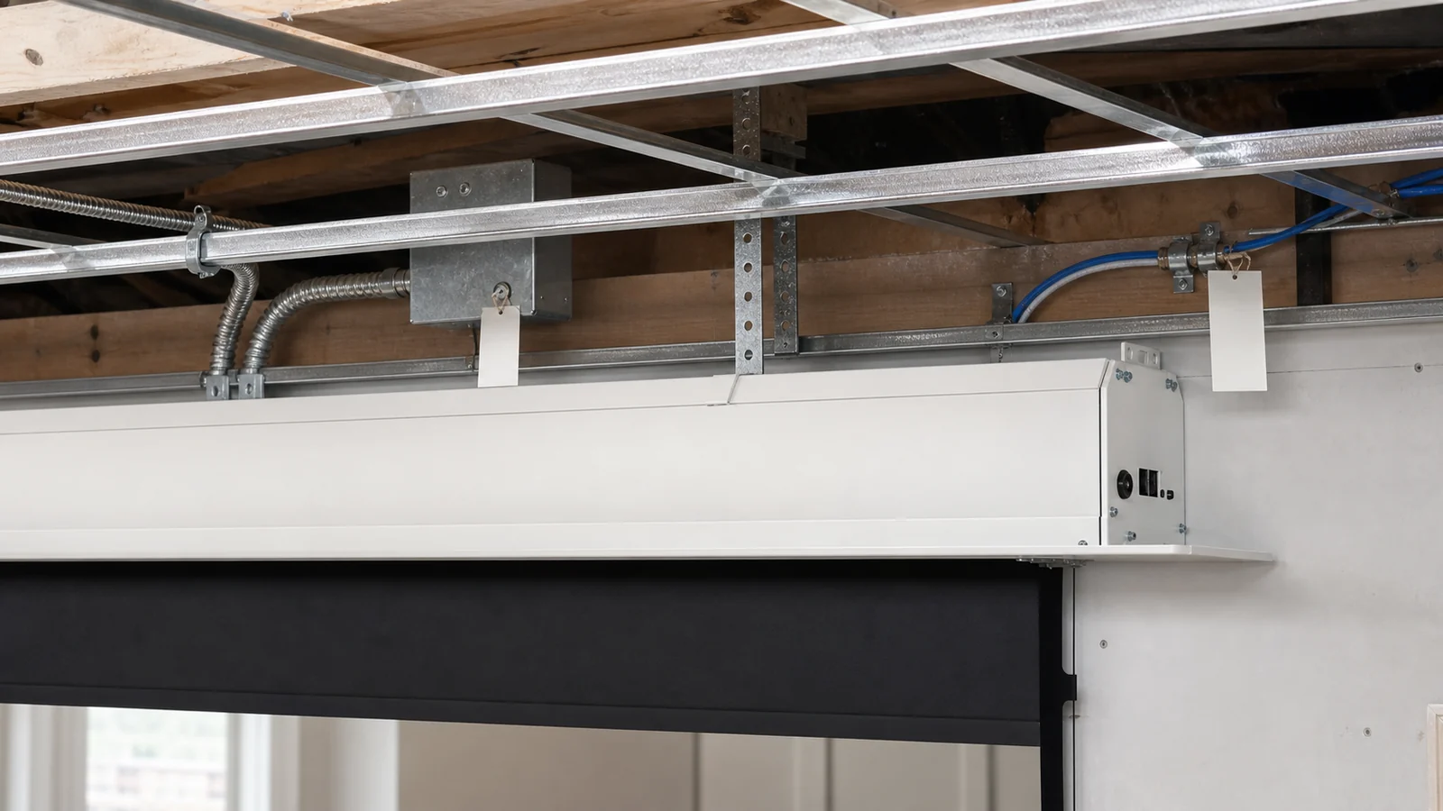
Route control cabling before closure and maintain the separation from mains wiring required by local rules and the interface manufacturer. Label both ends with room, device and function. Leave service loops only where they remain accessible and do not interfere with the roller or screen travel.
Our motorized screen control guide compares the methods and lists factory-confirmation questions.
Provide Service Access
Future technicians may need to reach the power connection, receiver, external controller, brackets or motor end. Confirm what is serviceable for the selected model and design an access route that does not require destructive ceiling work.
Photograph the open ceiling with a reference scale before closure. Record cable routes, junction locations and spare conduit in the handover package. These images are often more useful than a perfect as-built line drawn after the fact.
Pre-Close Inspection
Before walls or ceilings close, verify:
- screen centerline and housing elevation;
- structural support and bracket zones;
- power route, entry end and accessible connection location;
- control and spare pathways;
- cable separation, support and fire stopping;
- access-panel location and removal path;
- projector/trigger pathway where required;
- photographs and labels;
- final model documentation against the rough-in.
Do not energize temporary or incomplete wiring merely to “see if it works.” Testing should occur after safe termination by the responsible trades.
Commissioning and Handover
During commissioning, qualified personnel should verify the supply and protective measures, then test the screen using the model-specific sequence. Observe deployment and retraction, stop behavior, bottom-bar clearance, control priority and full-system operation.
Do not change motor limits without the exact procedure and authorization for the supplied motor. If travel is wrong or the screen stops unexpectedly, use the safe external checks in our troubleshooting guide and contact technical support.
Handover should include:
- model and serial/order reference;
- wiring diagram and installed control method;
- breaker or isolation identification where appropriate;
- remote, switch and controller instructions;
- access location and open-ceiling photos;
- commissioning result and responsible contacts.
FAQ
Does a motorized projection screen need a dedicated circuit?
That depends on the screen rating, project design and local electrical code. The electrical designer or qualified electrician should determine the circuit arrangement from the exact model documentation.
Which end of the screen needs power?
It varies by product and motor configuration. Confirm the power-entry end on the approved drawing before rough-in; do not assume it can be changed during installation.
Can low-voltage control cable share a conduit with mains power?
Separation and conduit rules depend on local code and the circuit types. The responsible electrical professional must design the route; do not use a generic screen guide as the code basis.
Can I add dry contact or a 12V trigger later?
Only if the ordered controller supports it and a cable path remains available. Confirm the interface and route a suitable pathway before closure whenever future integration is likely.
Should installers adjust screen limits during commissioning?
Only when the supplied model's instructions require it and the responsible technician has the exact procedure. Blind limit adjustment can cause incorrect travel or damage.
Confirm Wiring Before the Ceiling Closes
Send MGF the selected screen model, destination power standard, desired control method, housing location and construction drawings. MGF can confirm available configuration information and the documents required for coordinated installation.
Request wiring information for a motorized screen.
---