Projection Screen Casing Size, Black Border and Drop: What to Specify
---
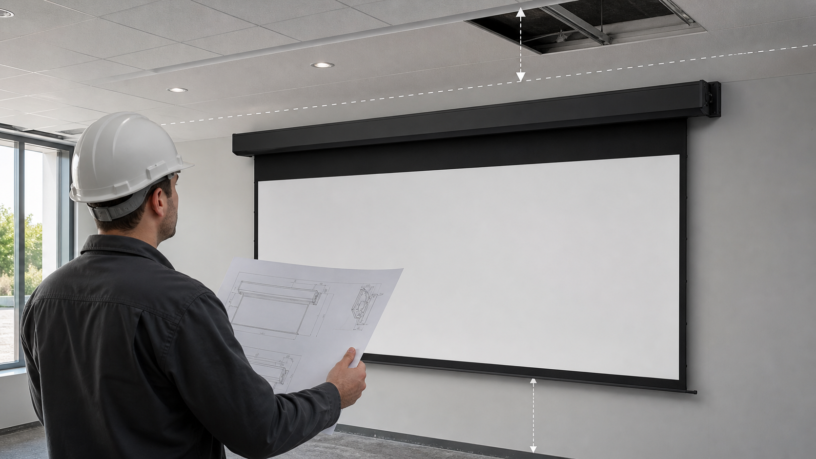
Projection screen drawings often fail because the visible image is specified but the housing, border, drop and service clearances are not. Installers then receive a screen that has the correct nominal size but cannot fit the ceiling, wall, trim opening or projector geometry.
In This Guide
Quick Answer
Specify four layers separately: visible image width and height, black border or masking, extra drop or leader, and total casing or frame dimensions. Add mounting points, cable entry, service access, projector position and surrounding clearances. Never scale a casing from a product photograph; use the exact model drawing and approval revision.
For the broader installation workflow, see the Installation & Troubleshooting Hub, the in-ceiling installation checklist and the motorized wiring guide.
Who This Guide Is For
This guide is for AV integrators, distributors, contractors and project buyers who need a documented selection and project-planning path for this topic before requesting a quotation.
1. Define the Visible Image First
Record image width, image height and aspect ratio. If the project uses a black border, state whether the dimensions refer to the active image or the fabric including the border. Use the same convention in the RFQ, drawing, purchase order and site acceptance form.
The size and aspect-ratio guide is useful for the first calculation. A 16:9 image, for example, does not describe the casing length, top drop, brackets or bottom bar. Those are separate fields.
2. Explain Black Border and Masking
Black border can visually frame an image and help the viewer identify the active area. On fixed frame screens, the border is part of the frame or surface layout. On electric screens, a black top drop or leader may place the image at the required height. A border can also reduce the nominal visible image if its size is changed.
Ask for a drawing that marks the active image, border, total fabric, roller or frame edge and bottom bar. Do not assume a “120-inch screen” has the same active image on every product family.
3. Define Drop or Leader Separately
Drop is the extra material above the image that positions the image at the correct height. It may be fixed, adjustable or model dependent. The amount should be tied to the installation type, room sightlines and the selected housing. A long leader can affect casing location, bottom-bar travel and trim clearance.
For a recessed or in-ceiling screen, confirm whether the drawing shows the casing, trim flange, access opening, finished ceiling and service space. Use the limit-setting and commissioning guide after installation; do not use limit adjustment to compensate for a wrong physical opening.
4. Capture Casing and Mounting Dimensions
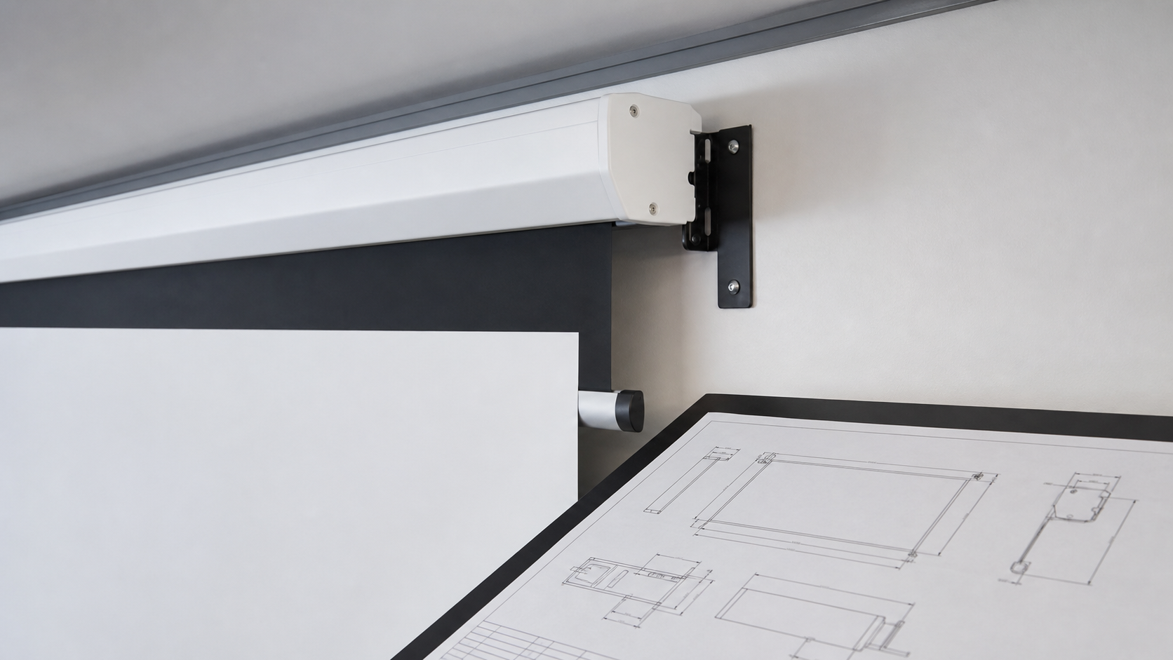
Request the exact housing width, height, depth, bracket spacing, mounting direction, cable-entry location and minimum clearance. For fixed frame screens, request overall frame width, height, depth, border and wall stand-off. For floor-rising products, include base footprint and the space needed for the screen to rise without obstruction.
The floor-rising guide explains why the enclosure and image geometry must be coordinated. For electric screens, the electric screen range is a product starting point, not a substitute for the model drawing.
5. Add Service and Coordination Zones
The installer needs enough room to mount, level, wire, test and later service the screen. Draw the projector beam, light fixtures, HVAC, sprinklers, ceiling grid, access panels and nearby joinery. A screen that physically fits may still be impossible to remove or adjust.
Record the power location and control route. The control integration guide covers local switches, remote control and optional interfaces; the selected controller must be confirmed rather than assumed.
Measurement Schedule
| Specification field | Required information |
|---|---|
| Active image | Width, height and aspect ratio |
| Border | Left, right, top and bottom border convention |
| Drop/leader | Length, fixed or adjustable, image height target |
| Housing/frame | Overall width, height, depth and mounting points |
| Mounting | Wall, ceiling, recessed, fixed frame or floor rising |
| Cable/control | Power entry, local control, remote or integration method |
| Service | Access panel, removal path and working clearance |
| Environment | Ceiling type, wall condition, light, HVAC and obstructions |
| Revision | Drawing number, date, approval owner and purchase-order reference |
MGF Product Direction
MGF can compare suitable product directions once the project brief confirms visible image size, aspect ratio, projector geometry, material direction, mounting condition, control requirements, quantity and destination market. The final quotation should identify the exact model, compatible material, drawing and approval information rather than treating a generic guide as a product specification.
Project / OEM Checklist
- visible image width, height and aspect ratio;
- projector model, lens position and image geometry;
- room or venue use, seating and ambient-light condition;
- proposed material, structure, mounting and service access;
- power, control and installation responsibility where relevant;
- required quantity, destination market, drawing revision and approval owner.
Continue Your Project Planning
- Installation & Troubleshooting Guides
- Electric Projection Screens
- Conference Room Applications
- Factory & Production
- In-Ceiling Installation Checklist
- Motorized Screen Troubleshooting Guide
- Contact MGF Screens
FAQ
Is casing size the same as screen size?
No. Screen size may refer to visible image or diagonal, while casing includes the roller, shell, brackets and other non-image components.
Does more drop make the image larger?
No. Drop changes the vertical position of the image; it does not automatically increase active image width or height.
Can the installer cut the ceiling opening from a catalogue photo?
No. Use the exact model drawing and approval revision.
What if the opening is already built?
Send the measured opening, access route, ceiling build-up and projector position to MGF before ordering. The selected model may need to change.
Request a Drawing-Based Specification Review
Send the target image, border and drop, ceiling or wall condition, available opening and control requirements to MGF via the Contact page. Ask for the model drawing and installation limits before the opening is closed.