Motorized Projection Screen Control Integration Guide
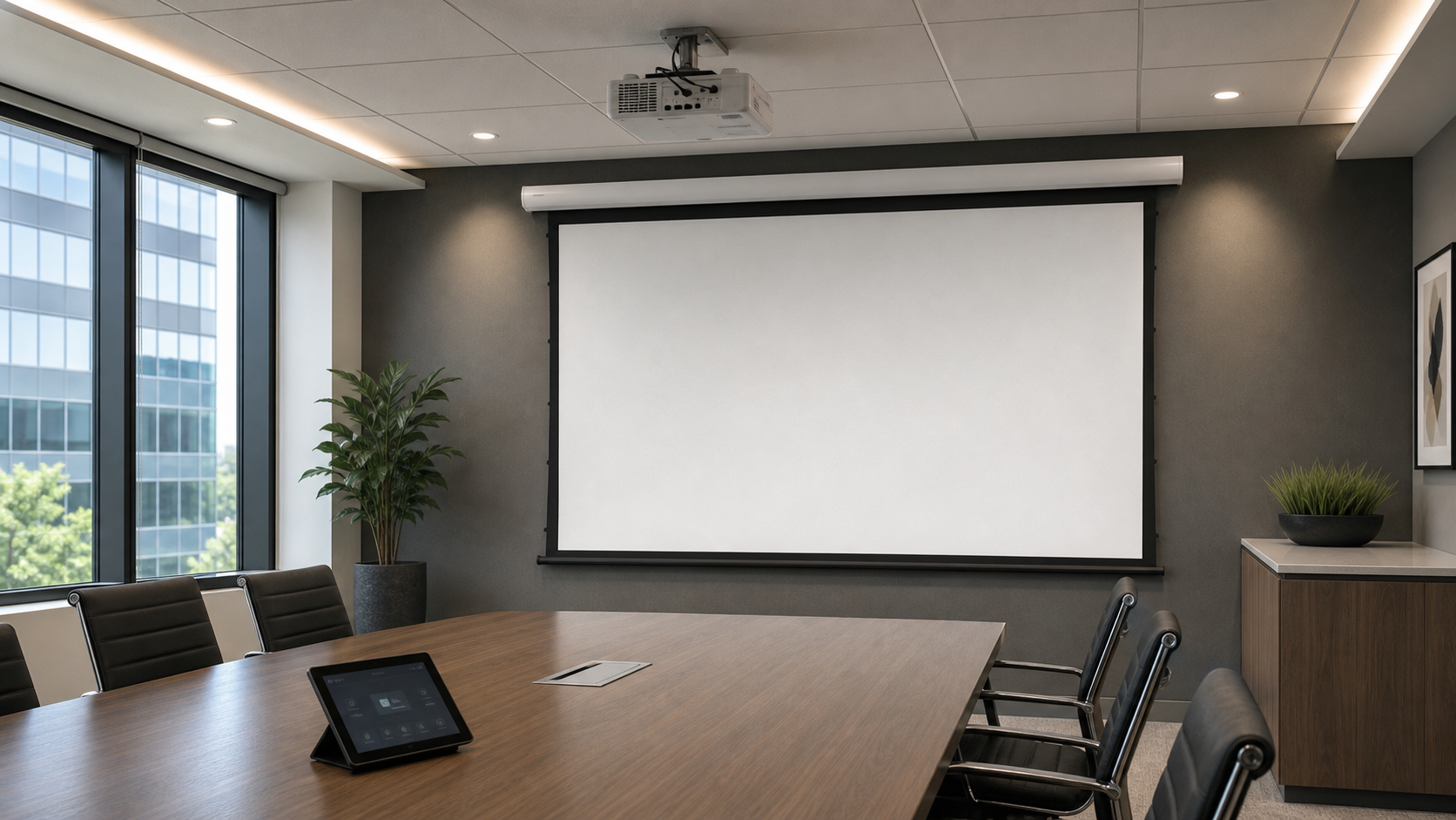
Motorized projection screen control must be coordinated with the exact screen model, motor, receiver, power supply, room controller and site wiring. IR, RF, projector trigger, dry contact and RS-485 are different interfaces; none should be assumed interchangeable. Use this guide to define the operating sequence, confirm the supported interface, assign wiring and programming responsibility, and approve the documents needed before procurement or ceiling closure.
In This Guide
Start With the Operating Sequence
Write the room behavior before choosing an interface. State what happens when presentation mode starts, when the screen reaches its lower limit, when the projector or controller is unavailable, and how the screen is operated locally during service. This sequence becomes the common reference for the supplier, electrician, installer and AV programmer.
- User selects the required room mode.
- The room controller or local control issues the screen command.
- The screen travels to the approved limit without obstruction.
- The projector and room sequence continue according to the approved timing.
- A local fallback remains available for testing and service.
- The screen retracts safely and the final state is recorded.
Choose the screen family before finalizing control. Compare Electric Projection Screens, then confirm the exact model, mounting condition and available control interface in the quotation.
Control Interface Confirmation Matrix
This matrix is a coordination checklist, not a promise that every model supports every interface. The approved model documentation controls the final decision.
| Interface | Typical project role | Confirm before approval | Record in submittal |
|---|---|---|---|
| IR | Line-of-sight local or rack-based command | Receiver position, command set and visibility | Receiver location and control path |
| RF | Wireless local operation | Matched transmitter/receiver, frequency and site range conditions | Receiver model, pairing method and fallback control |
| Projector trigger | Screen follows projector state | Signal type, voltage, polarity, timing and exact-model compatibility | Trigger source, cable route and expected sequence |
| Dry Contact | Relay or room-control command | Contact logic, terminal definition, relay requirement and isolation | Terminal map and responsible relay provider |
| RS-485 | Serial command, addressing or multi-room integration | Protocol, command list, address method, cable type and termination | Protocol revision, address schedule and programmer owner |
For cable-route and termination planning, use the Motorized Screen Wiring and Commissioning planning guide. Never copy terminal definitions from another model.
Power, Wiring and Physical Coordination
| Coordination item | Decision required | Approval evidence |
|---|---|---|
| Power supply | Voltage, frequency, feed, isolation point and party providing final connection | Electrical schedule and exact model data |
| Control cable | Cable type, route, separation, length allowance and labeling | Reflected ceiling or room-control drawing |
| Wiring location | Screen terminal, receiver, junction box, rack or relay position | Coordinated plan and section |
| Service access | Reachable receiver, isolation point, terminals and removable access area | Access detail before finishes close |
| Local override | Approved method for first power-up, testing and maintenance | Commissioning sequence and handover note |
Do not finalize wall, ceiling or furniture closure until the current wiring diagram and service route have been reviewed for the selected screen.
Control Responsibility Matrix
Assign each task by name. “By others” is not sufficient unless the responsible trade and acceptance owner are identified.
| Scope | Screen supplier | Electrician / installer | AV programmer / integrator | Client / consultant |
|---|---|---|---|---|
| Model and supported interface | Confirm current product documentation | Review installation impact | Review controller compatibility | Approve selected direction |
| Power and containment | State model requirement | Provide and terminate approved site scope | Identify control-cable needs | Approve coordinated drawing |
| Control hardware and programming | Identify included screen-side components | Install assigned components | Provide relays, gateways or programming in its scope | Approve operating sequence |
| Testing and handover | Provide model instructions | Verify installation and local operation | Verify integrated sequence | Witness and accept recorded result |
Project Submittal Package
The submittal should connect the product, power, control, wiring and responsibility records. Use the Projection Screen Submittal Drawing and Technical Package Checklist as the document index.
- approved screen model, visible image and housing drawing;
- current wiring diagram and terminal map;
- supported interface and protocol or command list where applicable;
- power requirement, cable route and wiring location;
- responsibility matrix covering supply, installation, programming and sign-off;
- operating sequence, local fallback and commissioning checklist;
- drawing, protocol and document revision numbers;
- open items with an owner and required decision date.
Commissioning and Handover Sequence
- Verify the exact installed model, wiring revision and safe mechanical path.
- Test local operation before connecting the final room-control sequence.
- Verify up, stop and down commands plus the approved limits.
- Test the selected IR, RF, trigger, Dry Contact or RS-485 interface.
- Test loss-of-control or power-interruption behavior and the local fallback.
- Run the complete room sequence and record the result.
- Deliver the final drawings, labels, settings, command list and responsible contacts.
If the screen stops against an obstruction, moves unexpectedly or cannot be isolated safely, stop repeated operation and follow the current model service procedure.
Control Integration RFQ Fields
| RFQ field | Information to provide |
|---|---|
| Screen and application | Target screen family or model, room use, visible size, mounting and quantity |
| Control protocol | IR, RF, trigger, Dry Contact, RS-485 or room-control requirement; include platform and protocol revision where known |
| Power supply | Project voltage/frequency, feed and isolation approach, subject to model confirmation |
| Wiring location | Terminal, receiver, junction box, rack or relay location plus cable route and access |
| Integration party | Named electrician, installer, AV programmer, consultant and final acceptance owner |
| Required documents | Drawing, wiring diagram, terminal map, protocol/command list, installation instructions and commissioning record |
| Commercial record | Quantity, destination, target schedule, branding or OEM scope and quotation revision |
FAQ
Can any motorized screen connect to RS-485?
No. Confirm the exact supported protocol, terminal definition, addressing method and command documentation for the selected model.
Is a projector trigger the same as Dry Contact?
Not necessarily. The signal type, voltage, polarity, timing and relay requirement must be checked for both devices.
Can control wiring be completed before the screen arrives?
The route and containment can be coordinated early, but final cable selection and termination must follow the approved model drawing and interface documentation.
Who should own final integration testing?
The project should name the integration party and acceptance owner. The supplier confirms product-side information; site trades remain responsible for their assigned installation, wiring and programming scope.
Confirm Control Compatibility Before Procurement
Send the screen model or target family, control platform, required protocol, power supply, wiring location, projector model, room sequence, responsible integration party, quantity and destination.
Contact MGF Screens for a control compatibility and submittal review.