Motorized Projection Screen Limit Setting and Commissioning Guide
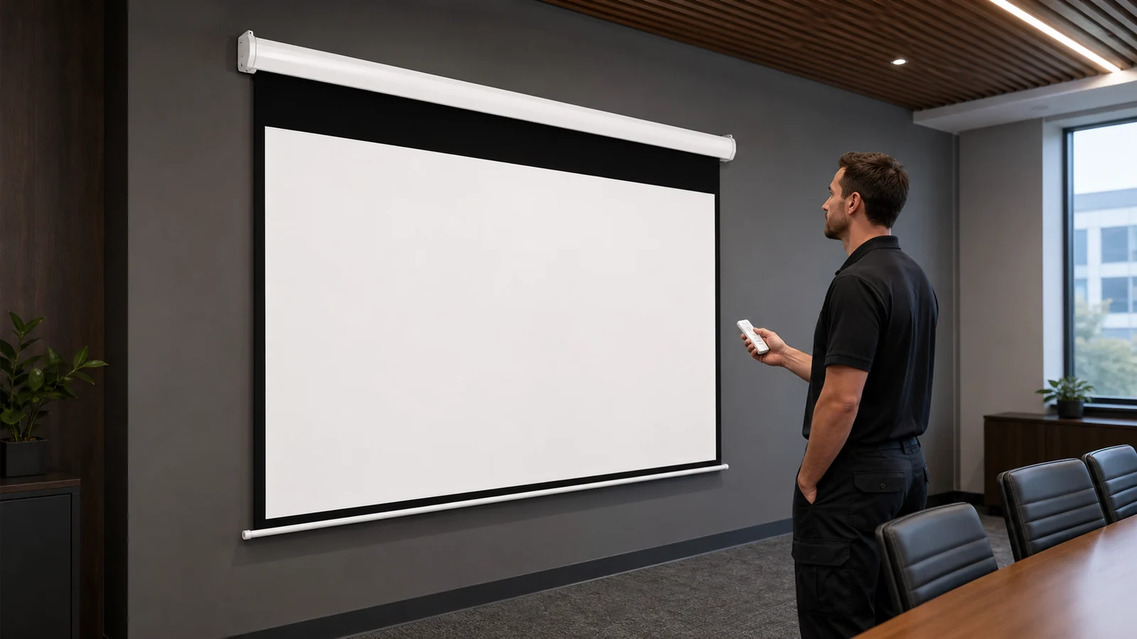
Upper and lower limits define where a motorized projection screen stops. Incorrect adjustment can leave the bottom bar too high, drive material farther than intended or interfere with housing and tension systems. There is no safe universal “turn this screw clockwise” procedure: motor types, access points and adjustment logic differ.
This guide covers commissioning decisions and evidence. Limit changes must follow the exact motor/screen instructions and be performed by authorized, qualified personnel.
In This Guide
First Decide Whether Adjustment Is Needed
Do not adjust limits simply because a new screen has arrived. Many products are factory set. First verify:
- correct model, size and installation orientation;
- housing and bottom bar are level;
- no packaging or obstruction remains;
- power and controls match the order;
- screen travels without rubbing or mechanical resistance;
- desired image position is within permitted product travel;
- the supplier authorizes site adjustment.
If travel changed after installation or the screen stops midway, use the troubleshooting guide before assuming the limit is the cause.
Commissioning Sequence
| Stage | Check | Stop condition |
|---|---|---|
| Documentation | Exact motor manual and approved drawing | Procedure or motor identity is uncertain |
| External inspection | Level, clearance, fabric tracking and bottom bar | Obstruction, damage or uneven mounting |
| Control check | Local and ordered remote/system controls | Unexpected direction or conflicting commands |
| Travel observation | Full movement from safe position | Noise, binding, severe skew or overtravel risk |
| Authorized limit work | Model-specific method only | Result differs from instructions |
| Repeatability | Several normal cycles if procedure requires | Stop position drifts or mechanism strains |
| Handover | Record final position and responsible technician | Documentation incomplete |
Define the Lower Position
The visible image should align with sightlines and furniture while keeping the bottom bar clear of people, doors and equipment. Do not lower beyond the material or tension system's designed travel to obtain a larger image. The approved drawing should identify visible height, black drop and final bottom position.
Define the Upper Position
The screen should retract to the position intended by the manufacturer without the bottom bar striking, disappearing incorrectly into or loading the housing. Stop immediately if the product sounds strained or the bar no longer follows the documented position.
Coordinate Controls
Test the local control first, then remote, trigger, dry contact or serial integration where supplied. Confirm up/stop/down direction and what happens when competing commands occur. The control integration guide explains interface planning; available functions vary by controller.
What Not to Do
- Do not use instructions from another brand or motor;
- do not guess adjustment direction or number of turns;
- do not hold a command while the screen is obstructed;
- do not pull the bottom bar by hand;
- do not open the housing or work on live parts without authorization;
- do not repeatedly cycle a screen showing noise, heat, smell, skew or binding;
- do not use limit adjustment to compensate for an unlevel installation.
Commissioning Record
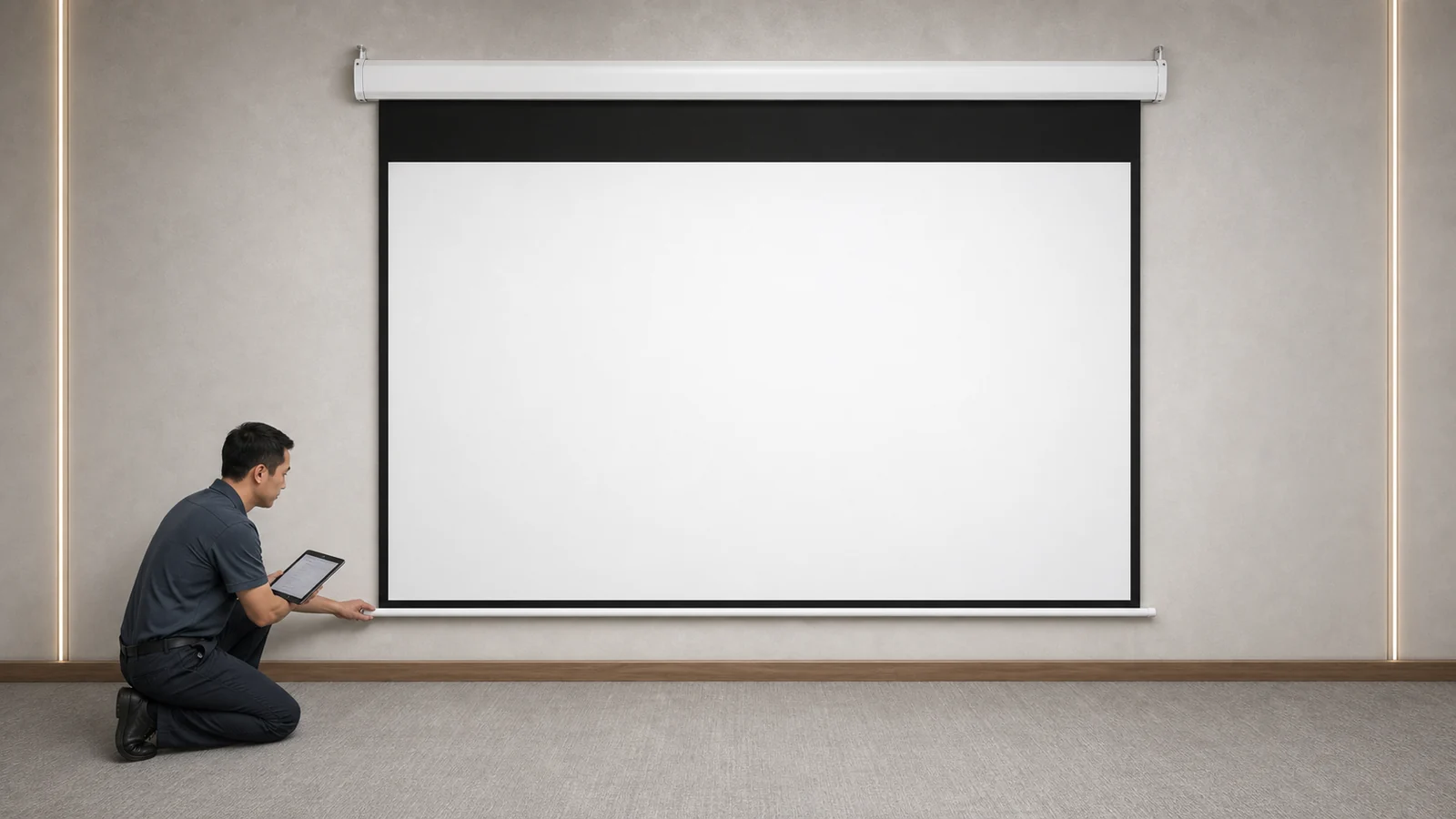
Record screen model/order reference, motor/control identification, installer, date, mounting level, final upper/lower position, tested control methods, observed travel, any authorized adjustment and the document revision used. Photograph the final deployed position without treating the image as dimensional evidence.
For recessed projects, include access and wiring records from the pre-wire guide.
FAQ
Are motorized screen limits factory set?
Many are, but configuration varies. Verify the exact product documentation and supplier instructions before making any change.
Which adjustment changes the upper or lower limit?
That depends on the motor. Do not rely on color, position or instructions from another model; obtain the exact procedure.
Why does the screen stop too high?
Possible causes include intended factory travel, limit configuration, control behavior or obstruction. Confirm documentation and external conditions before adjustment.
Can an AV installer set the limits?
Only when authorized for the selected product, using the exact instructions and safe working practices. Electrical rules and warranty conditions may also apply.
What if the stop position changes after commissioning?
Stop repeated adjustment, document the behavior and contact the supplier. Drift can indicate a control, motor or mechanical issue requiring diagnosis.
Obtain the Exact Commissioning Procedure
Send MGF the model/order reference, motor/control information, installed position and observed travel. MGF can confirm whether site limit adjustment is permitted and provide the applicable documentation.
Request motorized screen commissioning support.
---