OEM Projection Screen Engineering Drawing Approval Process

---
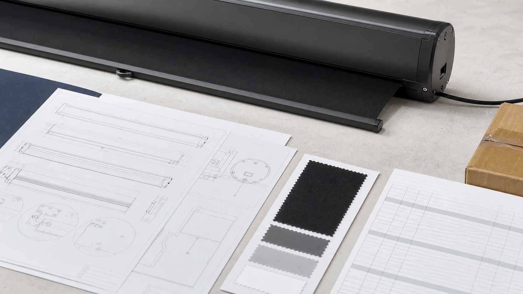
An engineering drawing approval is the point where a projection screen moves from a commercial idea to a defined physical product. The drawing should show what the buyer is approving, what the installer must build around and which assumptions still need an answer.
In This Guide
Quick Answer
Review the drawing in this order: product identity, visible image, material and border, casing or frame, mounting and clearances, power and control, service access, accessories, revision status and responsibility split. Record comments on the drawing or a formal comment log. Release the approved revision to manufacture only after all critical comments are closed.
Use the technical submittal checklist as the document baseline. The OEM RFQ guide should define the commercial scope that the drawing must reflect.
Who This Guide Is For
This guide is for AV integrators, distributors, contractors and project buyers who need a documented selection and project-planning path for this topic before requesting a quotation.
Stage 1: Confirm the Product Identity
Check model or configuration code, product family, quantity, room or area, drawing number, revision and status. A “for review” drawing must not be mistaken for an approved production drawing. Confirm whether the drawing covers a single size or a group of rooms.
If the project uses private labeling, keep the MGF internal model reference available even when the visible label changes. This preserves traceability for inspection and service.
Stage 2: Review Visible Image and Material
Confirm active image width, height, aspect ratio, black border, top drop or leader and projection direction. Check whether the dimensions refer to active image, fabric, frame or casing. Then verify the material name and approved sample code.
Do not approve “white fabric” or “ALR” as a complete material description. The surface family, backing, orientation and compatible structure may affect the image. Use the material sample evaluation checklist when the material is still under review.
Stage 3: Check Housing, Frame and Mounting
For electric screens, review casing width, height, depth, bracket positions, cable entry, bottom bar, mounting direction and service access. For fixed frames, review overall frame size, border, depth, wall stand-off and tensioning details. For in-ceiling screens, add finished ceiling, trim, opening and removal path.
The casing, black border and drop guide provides a useful measurement sequence. Do not scale a drawing from a photo or an old project.
Stage 4: Coordinate Projector and Room Conditions
Show the screen in the room elevation or plan when projector throw, lens shift, ceiling height, sightlines, windows or furniture affect the choice. The viewing distance and image height guide helps confirm the image position.
For short-throw or UST systems, add the projector lens location and surface direction to the review. For acoustic transparent screens, include speaker wall depth and the closest seat. The drawing should expose coordination risk before the wall or ceiling is closed.
Stage 5: Review Power, Control and Responsibility
Record the intended power entry, local control, remote method and integration requirement. If the project expects trigger, dry contact, RF, IR or serial control, mark the interface as confirmed, pending or excluded. The control integration guide explains the questions; it does not make every interface standard.
Create a responsibility table for factory, electrician, installer, AV programmer and client. Unassigned cable and commissioning tasks are common causes of site delay.
Stage 6: Close Comments and Release the Revision
Use a comment log with item number, reviewer, response, drawing change, owner and status. Reissue the drawing when a critical field changes. The approved revision should be linked to the purchase order, inspection record and packing list.
Drawing Approval Table
| Review area | Evidence to check | Release condition |
|---|---|---|
| Identity | Model, room, quantity and revision | No ambiguity |
| Image | Active size, ratio, border and drop | Matches approved scope |
| Material | Sample code and projection direction | Sample or condition recorded |
| Structure | Casing/frame and mounting | Fits room and access route |
| Controls | Power, control and responsibilities | Interfaces assigned |
| Coordination | Projector, sightlines and obstructions | Conflicts closed |
| Quality | Inspection and acceptance references | Test method identified |
MGF Product Direction
MGF can compare suitable product directions once the project brief confirms visible image size, aspect ratio, projector geometry, material direction, mounting condition, control requirements, quantity and destination market. The final quotation should identify the exact model, compatible material, drawing and approval information rather than treating a generic guide as a product specification.
Project / OEM Checklist
- visible image width, height and aspect ratio;
- projector model, lens position and image geometry;
- room or venue use, seating and ambient-light condition;
- proposed material, structure, mounting and service access;
- power, control and installation responsibility where relevant;
- required quantity, destination market, drawing revision and approval owner.
Continue Your Project Planning
- OEM & Procurement Guides
- OEM & ODM Projection Screens
- Quality Control
- Factory & Production
- Contact MGF Screens
FAQ
Who should approve a screen drawing?
The project’s designated buyer, consultant, AV integrator or owner should approve it according to the contract. The supplier should record the approval and revision.
Can production start with comments open?
Only when the project explicitly accepts the open items and they do not affect the product or installation. Critical geometry and material comments should be closed first.
What if the site opening differs from the drawing?
Stop and document the measured condition. Do not modify the product or opening informally; request a coordinated solution and revision.
Should the same drawing be reused for every room?
Use a controlled template, but verify room-specific size, projector, mounting, access and control conditions.
Request a Drawing Review
Send the project plan, room use, image size, projector data, material direction, mounting method, control expectation and approval format to MGF via the Contact page. The final drawing should be a shared installation and production reference.